This page contains the AQA GCSE Physics P4 Electric Circuits Kerboodle Answers for revision and understanding. This page also contains the link to the notes and video for the revision of this topic.
P.1 :Electrical charges and fields AQA GCSE Physics P4 Electric Circuits Kerboodle Answers: Page No. 51
1 a i because when you rub the insulator, electrons are transferred from one of the materials to the other material. Rubbing a polythene rod with a dry cloth transfers electrons to the surface atoms of the rod from the cloth. So the polythene rod becomes negatively charged.
ii a because rubbing a Perspex rod with a dry cloth transfers electrons from the surface atoms of the rod on to the cloth. So the Perspex rod becomes positively charged. Its positive charge is equal to the negative charge of the dry cloth.
b on rubbing with a dry cloth electrons transferred from glass rod to a dry cloth, so the glass is charged positive and a dry cloth acquired negative charge.
2 Then rod A attract rod B.
b Then rod A repel rod B.
3 a then attraction takes place. Because unlike charges attract each other.
b then attraction takes place. Because unlike charges attract each other.
c when a polythene rod is held near an ebonite rod then Repulsion takes place. Because Like charges repel.
4 a because both the rods contain same charge and like charges repel each other.
b If rod R is attract by rod X and Y, then rod X and Y are positively charged because unlike charges attract each other. If rod R is repel by both rod X and Y, then rod X and Y are negatively charged because like charges repel each other.
5 a We can get an electrostatic shock from charged objects, such as clothing made from nylon and other synthetic fibres. We can also get an electrostatic shock if you are charged and you touch something that is earthed. For example, when you walk on a vinyl floor or one covered with a nylon carpet you become charged because of friction.
You can earth yourself, and so get an electrostatic shock by touching a metal door handle, water pipe or even another person.
b because your clothing rubbing on the seat as you get out, this builds up a charge on your body which is discharged when you touch the ground. The solution is to keep hold of a metal part of the car body as you get out or take care not to wear clothing that generates a charge such as a Nylon jacket.
P4.2 Current and charge AQA GCSE Physics P4 Electric Circuits Kerboodle Answers : Page No. 53
1
1 Cell.
2 Switch.
3 Indicator.
4 Resistor.
2 a
b variable resistor.
c = 0.25*60 = 15C.
3 a An ammeter is used to measure the current in the circuit.
b Variable resistor is used to varied the current in the circuit.
4 a
b a current develops in the wires, electrons in the conduction band move from the positive to the negative pole through the light bulb. The electrons have an average drift velocity, carrying kinetic energy. In the resistance of the lamp they lose energy transferring it to the molecules of the resistor. The way electrons lose energy when decelerated is through photons, in the case of the light bulb infrared photons which make the lamp incandescent and then excite the electrons of the molecules of the resistor to high levels, enough to start de-exciting in visible light photon transitions.
Banner 1
Banner 2
Banner 3
P4.3 Potential difference and resistance AQA GCSE Physics P4 Electric Circuits Kerboodle Answers : Page No. 55
a V = IR
So R = 4/0.5 = 8ohm.
b
V = IR
R = 0.5/0.05 = 10ohm.
- W = 12/2 =6ohm resistance.
X = 80V potential difference.
Y = 6/3 = 2A current.
3 a R = 12/0.015 = 800ohm.
b I = 0.015*1200 = 18C
II E = Q*V = 18*12 = 216J.
4 a Resistance of the wire = 1/0.1 = 10ohm.
B = 1.6/10 = 0.16amperes.
ii p.d. = 0.42*10 = 420V.
P4.4 Component characteristics AQA GCSE Physics P4 Electric Circuits Kerboodle Answers : Page No. 57
1 a s Thermistor.
ii Diode.
iii So, the resistance of a filament lamp increases as the filament temperature increases.The atoms in the metal filament vibrate more as the temperature increases. So they resist the passage of the electrons through the filament more. The resistance of any metal increases as its temperature increases.
b I R = 0.5/0.1 = 5ohm.
ii R = 2/0.2 = 10ohm.
- We know that V = IR
So Resistance at this temperature = 9/0.6 = 15ohm.
b and its resistance decreases if its temperature increases (and increases if the temperature decreases).So if we increase the thermistor temperature then its resistance decreases and more current can flow through it and we got gain in ammeter reading.
3 the resistance of a light-dependent resistor (LDR) decreases if the light intensity increases and increases if the light intensity decreases if we covered a LDR its resistance increases so less amount of current flow through it and ammeter reading fall.
- a Initially the current is zero as we increase the potential difference and after some time on increasing further potential difference suddenly increase in a current takes place. In the reverse direction , the current is virtually zero.
b in the forward direction, the line curves towards they-axis. So the current is not directly proportional to the potential difference. The resistance changes as the current changes. A diode is a non-ohmic conductor. In the reverse direction, the current is virtually zero. So the diode’s resistance in the reverse direction is a lot higher than its resistance is in the forward direction.
P4.5 Series circuits AQA GCSE Physics P4 Electric Circuits Kerboodle Answers : Page No. 59
1 a The potential difference across the other bulb = 1.2-0.8 = 0.4V.
b I = 1/5 = 0.2A.
V = 1.5-1.0 = 0.5V.
2 a
2 = 3+2 = 5ohm.
ii I = 1.5/5 = 0.3A.
c As we know that V = IR
1.5 = 0.25(2+X) = 0.5+0.25X
Therefore 0.25X = 1.5-0.5 =1.0
And X = 1/0.25 = 4 ohm.
3 i R = 2+10 = 12ohm.
ii Total potential difference = 1.5+1.5 = 3V.
b I = 3/12 = 0.25A.
c For 2 ohm resistor p.d. = 0.25*2 = 0.5V.
For 10 ohm resistor p.d. = 0.25*10 = 2.5V.
d i R = 3+2+10 = 15ohm.
ii I = 3/15 = 0.2A.
iii For 2 ohm resistor p.d. = 0.2*2 = 0.4V.
For 10 ohm resistor p.d. = 0.2*10 = 2V.
For 3 ohm resistor p.d. = 0.2*3 = 0.6V.
- Adding more resistors in series increases the total resistance of the circuit. This is because the total potential difference is shared between more resistors, and as a result the potential difference across each of them is less than before. The current through the resistors is therefore less than before, and as the total potential difference is unchanged, the total resistance is therefore greater.
P4.6 Parallel circuits AQA GCSE Physics P4 Electric Circuits Kerboodle Answers : Page No. 61
1a 3 = 0.40-0.10 = 0.30A
- The bigger the resistance of the component, the smaller the current through it. The component that has the biggest resistance passes the smallest current. So the 3ohm resistor passes the most current
c 1/R = 1/1+1/2+1/6 = 10/6
So R = 6/10 = 0.6ohm.
2a A 6.0V battery is connected across a 12ohm resistor in parallel with a 24ohm resistor, circuit diagram for this circuit
b i the current through the 12ohm resistor is 0.50A
As we know that V = IR
I = 6/12 = 0.50A.
Ii the current through the 24ohm resistor I = 6/24 = 0.25A.
c the current passing through the cell 1/R = 1/12+1/24 = 3/24
So R = 24/3 = 8ohm.
I = 6/8 = 0.75A.
3 a i
i I1 = 6/2 = 3A.
I2 = 6/3 = 2A.
I3 = 6/6 = 1A
ii 1/R = 1/2+1/3+1/6 = 1
R = 1ohm.
I = 6/1 = 6A.
b 1/R = 1/2+1/3+1/4 = 13/12
R = 12/13ohm.
I = 6*13/12 = 6.5A
4 adding more resistors in parallel decreases the total resistance. This is because the total potential difference is the same across each resistor.
1/R = 1/2+1/3+1/6 = 1
Equivalent resistance R = 1ohm
AQAGCSEPhysics P4 Electric Circuits Summary questions: Kerboodle Answer Page No. 62
1 the resistance increases when the current increases, because the bulb is warmer, so the metal ions in the filament vibrate more and resist the passage of electrons through the filament more
2
a Its resistance increases if the current through it increases the filament bulb
b The current through it is proportional to the potential difference across it resistor
c resistance decreases if its temperature is increased is thermistor
d diode’s resistance depends on which way around it is connected in a circuit.
3 a circuit diagram with 2 resistors labelled P and Q in series with a battery of 2 cells
b In the circuit in part a, resistor P has a resistance of4.0 {l, resistor Q has a resistance of 6.0fl, and each cell has a potential difference of 1.5V. Calculate:
i 2 × 1.5 V =3.0 V
ii 4.0 Ω + 6.0 Ω = 10 Ω
iii 3.0 V/10 Ω
= 0.30 A
iv VP = (0.30 A × 4.0 Ω =) 1.2 V
VQ = (0.30A × 6.0 Ω =) 1.8 V
4 a circuit diagram with 2 resistors labelled R and S in parallel with one cell
i 2.0 V/8.0 Ω
= 0.25 A
ii 2.0 V/4.0 Ω
= 0.50 A
Iii (0.50 A + 0.25 A =) 0.75 A
5 a i 0.010 A × 200 Ω = 2.0 V
ii 3.0 V – 2.0 V = 1.0 V
iii 1.0 V/0.010 A = 100 Ω
b i decreases as LDR resistance increases so total circuit resistance increases
ii p.d. across LDR = V – (I × R)
so RLDR p.d. across LDR ÷ current I
6 a circuit diagram of 3.0 V cell with 2 resistors labelled 100 Ω and 200 Ω in series, with voltmeter connected in parallel with 100 Ω resistor
b i (100 Ω + 200 Ω) = 300 Ω
ii 3.0 V/300 Ω
= 0.01 A
iii 0.01 A × 100 Ω
= 1.0 V
iv V100 Ω = 1.0 V
V200 Ω = 3.0 V – 1.0 V = 2.0 V
7 a i 3.0 V p.d. shared between LED and resistor,
VLED = 0.6 V when it emits light, p.d. across the resistor =
3.0 V – 0.6 V = 2.4 V
ii the current in the circuit is 2.4 V/1000 Ω
= 0.0024 A
b ~ VR = 2.4 V (as VLED = 0.6 V)
current = 15 mA so R = 2.4 V/0.015 A = 160 Ω
8a or almost zero ‘reverse’ R of LED very high, total R of LED and resistor \ much greater when LED in ‘forward’ direction so I much less when diode in ‘forward’ direction
b Working of circuit diagram: thermistor and variable resistor in series buzzer across thermistor
AQA GCSE Physics P4 Electric Circuits Practice questions: Kerboodle Answer Page No. 63
01.1 The material that gains___electrons_____becomes___negatively_____charged.
The material that loses___electrons_____becomes___positively_______charged.
01.2 A non-contact force repels ball b away from ball a
01.3 the force would still repel ball
b, but will be weaker than before
02.1 20 Ω (Ohms)
02.2
R1 = 20 Ω
R2 = 13.3 Ω
so total is 33.3 Ω
02.3 correct symbol across the bulb
02.4 3.0 C (Coulombs)
02.5
the voltmeter is in series with the coil of wire
03.2 to maintain a constant temperature
03.3 measures the current in amps measures the potential difference in volts using the formula R = V/I
03.4 only use low voltages on the power pack
DISCLAIMER
Disclaimer: I have tried by level best to provide the answers and video explanations to the best of my knowledge. All the answers and notes are written by me and if there is any similarity in the content then it is purely coincidental. But this is not an alternative to the textbook. You should cover the specification or the textbook thoroughly. This is the quick revision to help you cover the gist of everything. In case you spot any errors then do let us know and we will rectify it.
References:
BBC Bitesize
AQA GCSE Science Kerboodle textbook
Wikipedia
Wikimedia Commons
Join Our Free Facebook Group : Get A* in GCSE and A LEVEL Science and Maths by Mahima Laroyia: https://www.facebook.com/groups/expertguidance.co.uk/
For Free Tips, advice and Maths and Science Help
This page contains the detailed and easy notes for AQA GCSE Physics Electricity for revision and understanding Electricity.
Banner 1
AQA GCSE Paper 1: Complete Revision Summary
ELECTRICITY
Banner 2
4.2 ELECTRICITY
- Circuit Symbols
- Circuit Diagram
- Charge, Current, Resistance and
- Potential Difference
- Voltage-Current Graph of
- Resistor, Filament Bulb and diode
- Series Circuit
- Parallel Circuit
- Main electricity
- Power
- Energy Efficiency
- National Grid
- Static Electricity
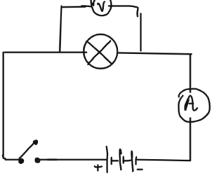
CIRCUIT DIAGRAM
- Draw a circuit diagram with a battery, bulb and a switch.
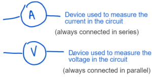
- How will you measure the current and potential Difference of the Circuit ?
CURRENT, POTENTIAL DIFFERENCE AND RESISTANCE
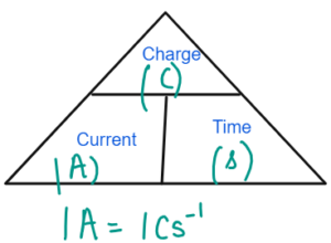
- Current is the rate of flow of charge measured in Ampere.
- One Ampere is the current flowing when one coulomb of charge flows through one second.
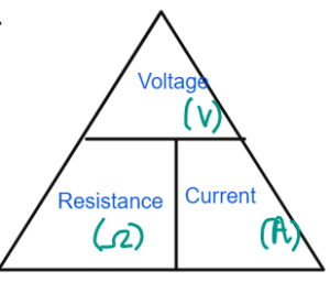
- Resistance is the obstruction to the flow of current measured in ohms
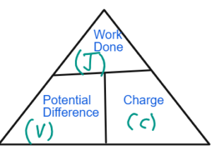
- Potential difference measured in Volts is the work done per unit charge.
- 1V = 1JC-1
- One volts is the potential difference when 1 J of energy is transferred per coulomb of charge.
Banner 3
CIRCUIT SYMBOLS
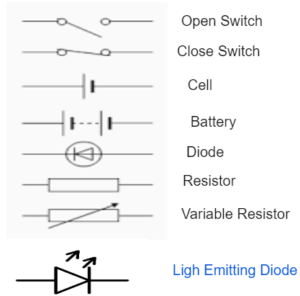
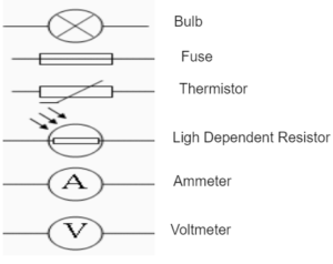
EXAMPLES
Q1 Calculate the current flowing when 4 C of charge flows for 2 minutes ?
I = Q/T = 4/2 X 60 S = 0.033A
Q2 Calculate the energy transferred when 2 V of potential difference creates a charge of 2 C
E = V x Q = 2 x 2 =4J
Q3 Calculate the resistance of the circuit when 4V of potential difference produces a current of 2 A.
R = V/I =4/2 = 2 Ω
Q4 Calculate the charge when 5A of current flows for 5 minutes
Q = I x T = 5 x 5 x 60 =1500C
Q5 Calculate the potential difference when 10 J of work done is done to move the charge of 5 C.
V = E/Q =10/5 = 2V
VOLTAGE-CURRENT GRAPH
Banner 4
Conductor
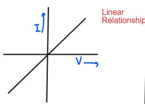
As the voltage increases, the current Increases. The resistance is constant.
Filament Lamp
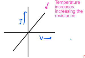
As the voltage increases, the current increases at the start but after that bulb gets heated and increase in temperature increases resistance so the current do not increases and the graph curves.
Diode
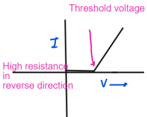
Diode conduct electricity in one direction. In reverse direction, the resistance is too high so no current flows. When it reaches a threshold voltage, the current starts to increases then linearlt.
SERIES AND PARALLEL CIRCUITS
Series Circuit

- Total Resistance is greater than individual: R 1+ R2 = R(Total)
- Current Across each component is the same: V(total)/R(Total)= I
- Voltages get divided between each component
Parallel Circuit
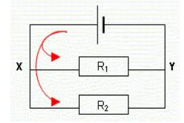
- Total resistance is less than individual = R(total) = R1R2/R1 +R2
- Voltage is same across is each component = V
- Current gets divided between the components
- I1 = V/R1 I2 = V/R2
Banner 5
EXAMPLE OF SERIES AND PARALLEL CIRCUITS
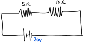
- Total Resistance RI + R2 = 15 Ω
- Voltage: 20V
- Current = 20/15 =1.33A
- Voltage across 5 ohms = 1.33 x 5 = 6.7V
- Voltage across 10 ohms = 1.33 X 10 = 13.3V
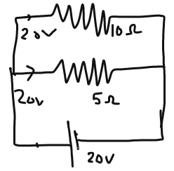
- Total Resistance R1R2/ R1 + R2 = 50/15 = 3.33
- Voltage: 20V
- Current = 20/3.33 =6A
- Current across 5 ohms = 20/5 = 4A
- Current across 10 ohms = 20/10 = 2A
MAIN ELECTRCITIY
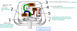
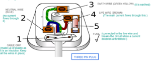
Outer casing is made up of plastic as It is an insulator and Pins are made up of brass as it is a conductor and resistant to corrosion
UK MAIN SUPPLY
Voltage = 230V
Frequency = 50H3
ELECTRIC POWER
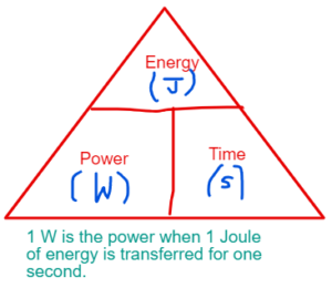
Electrical Power = V x I
(Voltage ) x (Current)
P = I2 x R [V= I x R]
P = V2/R
Q1 Calculate the current product by 200 W bulb if it generate a voltage of 10 v.
P = I x V
200/10 = I = 20
Q2 which is the fuse for this appliance. 12, 20, 23A or 25A
P = V x I
I = P/V = 200/10 = 20A
So the fuse of slightly greater than 20 A will be useful. So it has to be 23 A.
Baneer 6
DIRECT AND ALTERNATING CURRENT
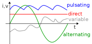
| DIRECT | ALTERNATING |
| Current that flows in one direction. | Current that changes direction. |
| Current in cell and batteries. | Current in the mains supply. |
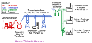
NATIONAL GRID
- A network of cable and transformers that transmits electricity from a power station to homes and buildings.
- Step up transformer is used to increase the voltage for transmission. As higher voltage will have less current and so less loss of energy due to heating effect of current.
Banner 7
STATIC ELECTRICITY
- Electricity due to the charge produced by rubbing.
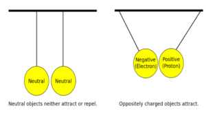
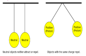
- Atom is neutral. Due to rubbing there is a movement of electrons from one surface to another.
- The surface that loose electrons become positively charged and the surface that gains electron become negatively charged.
Banner 8
LIKE CHARGES REPEL and UNLIKE CHARGES ATTRACT EACH OTHER
ELECTRIC FIELDS
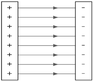
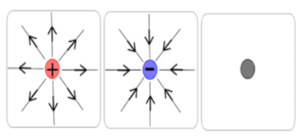
Electric Field of line always travel from positive to negative.
It is the area around a charge object where force of electricity can be felt.
Banner 9
TEST YOUTSELF
Q1 Sketch and explain the Voltage and Current graph of
- a) Resistor
- b) Filament Lamp
- c) Diode

Q2 What are the components of a three pin plug
Q3 What is the voltage and frequency of UK Mains Supply ?
UK MAIN SUPPLY
Voltage = 230V
Frequency = 50H3
Q4 How do your calculate efficiency of an appliance
Efficiency = Output Power/ Input Power x 100
Banner 10
Disclaimer:
I have tried my level best to cover the maximum of your specification. But this is not the alternative to the textbook. You should cover the specification or the textbook thoroughly. This is the quick revision to help you cover the gist of everything. In case you spot any errors then do let us know and we will rectify it.
References:
BBC Bitesize
Wikipedia
Wikimedia Commons
Image Source:
Wikipedia
Wikimedia
Commons
Flickr
Pixabay
Make sure you have watched the above videos and are familiar with the key definations before trying these questions. It is also good to time yourself while doing these questions so that you can work on the speed as well.
P4-Electric Circuits
- Static Electricity 1 MS
- Static Electricity 1 QP
- Static Electricity 2 MS
- Static Electricity 2 QP
- Current, Potentiagy Tl Difference & Resistance 1 MS
- Current, Potential Difference & Resistance 1 QP
- Current, Potential Difference & Resistance 2 MS
- Current, Potential Difference & Resistance 2 QP
- Current, Potential Difference & Resistance 3 MS
- Current, Potential Difference & Resistance 3 QP
